Jack Northrop (properly named John Knudsen Northrop) was born in 1895, and died in 1981.
He founded three aviation companies, the last two of which bore his name, and the last of which is still in existence as the Northrop Grumman Corporation. It’s said to be the fourth-largest defense contractor in the world today.
Almost all his life in aviation, Northrop was preoccupied (some would say obsessed) with the notion of an aircraft without a fuselage or tail structure – a pure ‘flying wing‘. It’s perhaps his personal tragedy that he was born when he was. Aviation materials and technology of his day simply weren’t equal to the task of producing a fully functional and safe aircraft in that shape or form. Today, of course, with computer-aided design, synthetic and artificial materials, and much more powerful engines and more capable electronics, the ‘flying wing’ is a reality, and looks set fair to be with us for a very long time to come in specialized military applications. Its most advanced application currently in service is Northrop Grumman’s own B-2 Spirit ‘stealth bomber’.
Here it’s shown from the refueling window of a US Air Force tanker.
At a total program cost per plane of well over $2 billion, this is also the most expensive aircraft ever built. All that money was required to develop and pay for the ultra-modern technologies involved in its construction. Without them, it would never have flown or been effective in its designated mission. That’s the challenge of the ‘flying wing’ – and its promise for the future. Those same technologies, in even more modern form, are now being applied to a whole new range of aircraft, which we’ll discuss in the next ‘Weekend Wings’, with particular reference to the US Air Force’s ‘New Generation’ or ‘Next Generation’ bomber requirement.
Let’s begin at the beginning. Jack Northrop worked for Lockheed and Douglas before he founded the Avion Corporation in 1928. While at Lockheed, he met Anthony Stadlman, who was enthusiastic about the possibilities inherent in a ‘flying wing’ design. It’s not certain whether Northrop was himself as enthusiastic at first, but there’s little doubt that he was inspired by Stadlman’s ideas, and adopted them in his own thinking. The two built a set of wings for a prototype ‘flying wing’, but didn’t proceed further with the design.
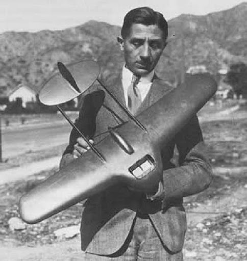
Stadlman is shown below in 1929, holding a model of his ‘flying wing’ design (which, since it still had tail and control surfaces, was not a ‘pure’ flying wing, but was as far as he could go with the materials and technologies available to him at that time).
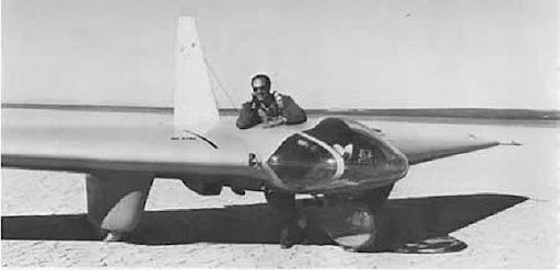
When Northrop founded the Avion Corporation in 1928, he began work on his own ‘Flying Wing’. He brought the newspaper magnate William Randolph Hearst to Avion as President, with himself as vice-president, and Hearst partly financed the development of the aircraft. The plane was not a true ‘flying wing’ in that it had tail-booms supporting conventional ailerons and rudders. However, its construction was very modern for the day, being all metal (duralumin), with the skin providing most of the structural strength of the aircraft. At the time, many aircraft were still being made with frames covered by fabric. Northrop experimented with two different power plants from Menasco Motors of Los Angeles. The first was an inverted Mark III Cirrus engine, in a pusher configuration, and the other a Menasco A-4 inverted engine driving a tractor propeller. The former configuration proved most useful in the prototype. The engine was completely enclosed within the wing, with cooling air passing through a tunnel in the wing. This significantly reduced aerodynamic drag. Two cockpits were provided, one on either side of the centrally-mounted seven-foot shaft connecting the pusher propeller to the forward-mounted engine, but one was covered over for the test flights. Northrop designed a retractable undercarriage for the aircraft, in co-operation with Menasco Motors, but in the event a conventional fixed undercarriage was used on the prototype.
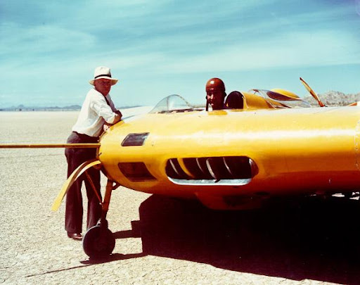
The prototype was tested at Muroc Dry Lake in the Mojave Desert (today the site of Edwards Air Force Base), with test pilot Eddie Bellande in the cockpit. Here Northrop (standing) is shown discussing the test flights with Bellande (in the cockpit).
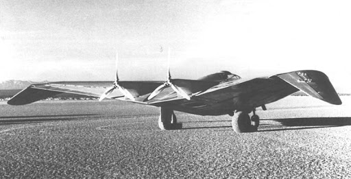
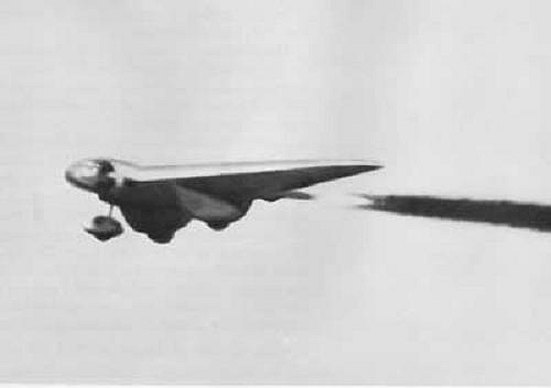
Here’s the ‘Flying Wing’ in the air in 1929, with Bellande at the controls.
The tests were generally very successful. The aircraft’s speed was described as ‘approximately 25% better than any other design of like power and capacity’, and flight characteristics were normal. Of course, this was due to the conventional ailerons and rudders, but the basic design of the ‘flying wing’ had been proven to be sound. Engineering data obtained from these flight tests would be used to develop the first true ‘flying wing’ aircraft a decade later. The test flights were completed in September 1930, and no further information is available on what happened to the prototype.
Northrop went on to form the Northrop Corporation in 1932, with financial backing from Douglas Aircraft Corporation. The new company developed several successful designs during the 1930’s, notably the Gamma and Delta transports.
By 1939, due to the difficult economic conditions of the 1930’s, Douglas had taken control of Northrop Corporation, and folded the smaller company into its own operations. Northrop proceeded to found a second Northrop Corporation, under his own control, with independent financing. He was now able to focus his efforts on further development of ‘flying wing’ designs.
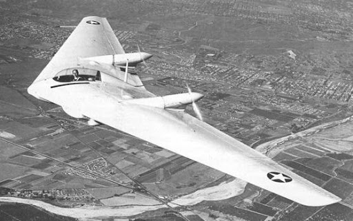
His first effort was the Northrop N-1M. This was the first true ‘flying wing’ in the USA, flying without any vertical control surfaces or rudders, and without ailerons mounted separately from the wings. It first flew in July 1941.
The drooped edges of the wings proved problematic during takeoff: as the aircraft rotated, the tips were lowered, so that they sometimes scraped the ground, causing damage. As testing progressed, a new straight-wing design was adopted, which proved just as capable of control in flight and eliminated this problem. The video clip below, taken in 1940, shows both versions of the N-1M in flight. I apologize for the music soundtrack that someone saw fit to record on it, but that’s YouTube for you!
Jack Northrop is shown below leaning on the prototype N-1M, speaking to a test pilot.
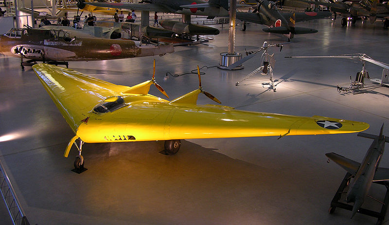
The only example of the N-1M was presented to the US Army Air Forces in 1945. It’s now on display in the Steven F. Udvar-Hazy Center of the National Air and Space Museum in Washington, D.C.
The N-1M proved that a ‘flying wing’ was feasible. It was a timely development. On April 11th, 1941, the US Army Air Corps put out a request for a new ultra-long-range high-speed bomber. It was to be capable of a round-trip mission of 10,000 miles, flying at a cruising speed of 275 mph, and with a maximum speed of 450 mph for shorter periods. Service ceiling was to be 45,000 feet. This aircraft was intended to allow the US to bomb European targets in the event that Britain fell to Nazi Germany.
The USAAC contract was initially offered to Boeing and Consolidated Aircraft Company (later Convair), but in May 1941 Northrop was also invited to submit design proposals. Jack Northrop’s answer was the XB-35, a ‘flying wing’ bomber of immense proportions for the day. It was a radical technological innovation, and no-one (except Northrop) was sure that it could be made to work: but the design looked so promising that Northrop received a contract in November 1941 to develop a prototype aircraft, with an option to order a second prototype, which was exercised in January 1942.
Because of the technological difficulties involved, the contract specified that a one-third-scale version of the XB-35 was to be built first, to investigate these issues. This became the Northrop N-9M, of which four were ultimately built. Based on the N-1M, but larger, and with more powerful engines, it would pave the way for its still larger sister. It first flew in December 1942.
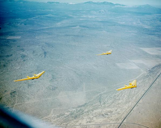
The aircraft proved underpowered, and the 260hp. Menasco C65-1 engines were replaced in later prototypes by two 400hp. Franklin engines. Both powerplants drove two-bladed pusher airscrews. The first prototype was lost in a crash in May 1943, the pilot being killed, but the three remaining aircraft were completed and continued their test flights. They are shown below in formation, date unknown.
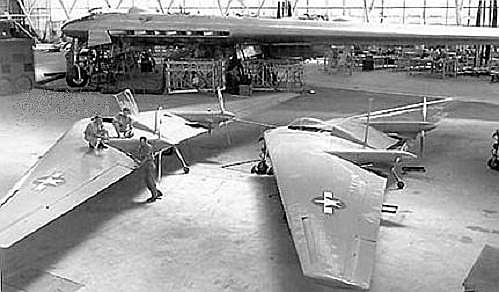
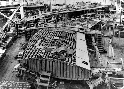
The N9-M prototypes accumulated valuable engineering data, which was fed back into the XB-35’s design and development. In the picture below, two of the N9-M prototypes are parked inside the assembly building. Behind them, the XB-35 prototype is taking shape.
Only one N9-M prototype survived the cancellation of the XB-35 program. It was restored to flying condition by a California museum in the 1980’s, and subsequently flown in air shows: the pictures and video clip below show it in action.
In 2006, an engine fire caused sufficient damage to render it non-airworthy. It’s not known when (or even if) it will fly again.
The N9-M tested a unique control configuration for the XB-35 project. As Wikipedia describes it:
Unlike conventional aircraft, flying wings cannot use a rudder for lateral control, so a set of butterfly-like, double split flaps on the trailing edge of the wingtips were used. When aileron control was input, they were deflected up or down as a single unit, just like an aileron. When rudder input was made, the two surfaces on one side opened, top and bottom, creating drag, and yawing the aircraft. By applying input to both rudder pedals, both sets of surfaces were deployed creating drag so that the airspeed or the glide angle could be manipulated.
While the N9-M was being built to test this design, detail design studies began for the XB-35. Here’s a 1941 Northrop design patent drawing.
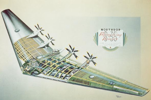
The huge wing would incorporate a crew cabin in a central section. A tail cone would protrude from the trailing edge of the wing, containing machine-guns operated from a remote sighting station for rearward defense. A total of nine crew would be carried: two pilots, a navigator, an engineer, a bomb-aimer, a radio operator and three gunners. Folding bunks were provided for crew rest during long-distance missions. The (rather indistinct and small-size) cutaway drawing below shows how the crew would be distributed. Note that there was no large central bomb bay: bombs would be carried in a number of smaller bays, distributed along the wing.
A new and very strong aluminum alloy would be used for the skin, adding strength to the airframe. Four 28-cylinder 3,000hp Pratt & Whitney R-4360 engines were intended to drive contra-rotating pusher propellers, eight in all (two per engine). Unfortunately, the contra-rotating propellers would prove enormously complex, causing major gearbox problems and being hard to control in flight.
Serious delays were experienced with refining the design and building the prototype. Some of these were allegedly caused by Jack Northrop’s continual diversion of members of the XB-35 team to work on other ‘flying wing’ designs (we’ll come back to them later).
The US Army Air Corps had initially specified that the first prototype was to be delivered in November 1943 and the second in April 1944. It soon became clear that this schedule was hopelessly optimistic. Nevertheless, in 1943 the USAAC decided to order 200 production-model B-35’s, and contracted with the Glenn L. Martin Company to produce them, as Northrop’s facilities were inadequate for mass production. In September 1943 13 pre-production YB-35’s were ordered from Northrop.
Delays in the development of the XB-35 forced the USAAC to cancel its order for 200 production aircraft in May 1944, as it was clear that the prototype would not fly before the end of World War II. However, the order for the 13 pre-production prototypes was allowed to stand, and the program was taken over by the Air Technical Services Command as a technology development exercise. Northrop also began studies on how to apply the new jet engines to the ‘flying wing’.
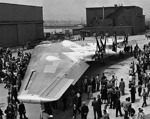
The first prototype XB-35 was finally rolled out in early 1946.
The aircraft flew in June 1946, over two and a half years behind schedule.
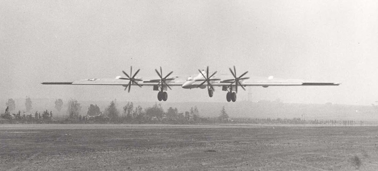
After only a few test flights, both prototypes had to be grounded and the propellers replaced with single units. However, these produced far less power than the double contra-rotating units, severely limiting the aircraft’s speed and performance. The single propellers may be seen in flight below.
To make matters worse, the engines used a very complex exhaust system to get their gases out of the rear of the wing. It gave immense problems, particularly with heat buildup, which were never fully resolved. The engines began to show signs of metal fatigue after only two years. In addition, the range and speed of the prototypes was less than called for by the US Army Air Corps specification: and the reciprocating engines of the XB-35 had been made obsolescent by the advent of jet engines. To complicate matters further, the XB-35 had no single large bomb bay, so it could not accommodate the very large early nuclear weapons. Other bombers such as the Boeing B-29 Superfortress and Convair B-36 could do so, and this factor, more than any other, is probably what ultimately doomed the XB-35 program and its successor.
However, Jack Northrop and his team of designers had been hard at work developing a jet-powered version of the XB-35. They succeeded in persuading the US Army Air Force (as the USAAC had now been renamed) to fund development of this project. The XB-35 and YB-35 programs were cancelled in July 1949, and the two XB-35 prototypes were scrapped in August of that year. The first YB-35 pre-production prototype had flown in 1948. It, and the second YB-35 aircraft, were also scrapped in 1949. However, the remaining eleven YB-35 fuselages were retained for conversion to jet propulsion as part of a new program – the Northrop YB-49.
The YB-49 program got underway as early as 1944, as mentioned above, with the cancellation of the USAAF order for 200 production-model B-35’s. It would apply new jet propulsion technology to the ‘flying wing’. Instead of building prototype aircraft ‘from scratch’, two of the already-contracted YB-35 pre-production aircraft would be converted for this purpose.
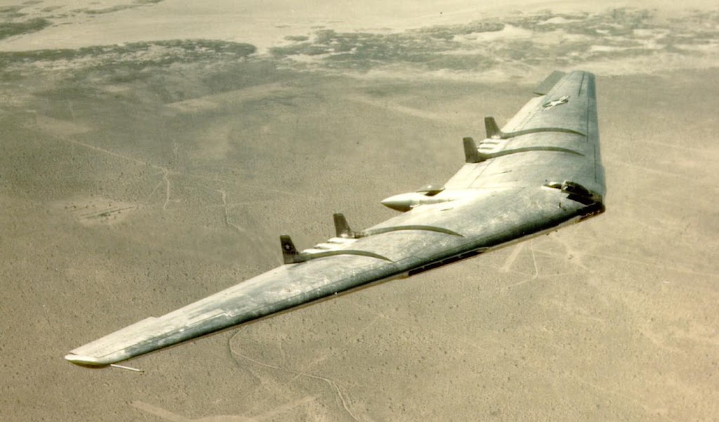
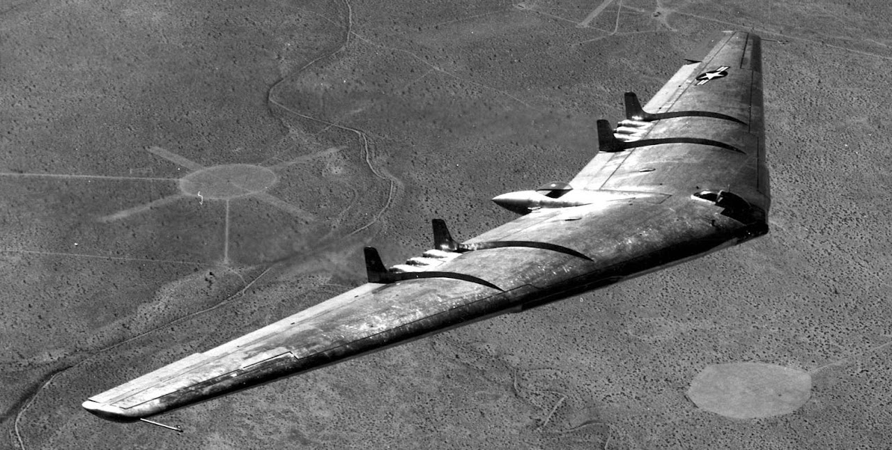
Work on the YB-49 proceeded much more quickly than on the troubled XB-35. It was redesigned to accommodate eight Allison/GE J-35 axial-flow turbojet engines, each producing 4,000 pounds of thrust for a total of 32,000 pounds. Unfortunately, the thick airfoil section of the XB-35 was retained. This had been designed for a cruising speed of only 240 mph, which severely restricted the YB-49’s Mach limit and maximum speed. Four vertical stabilizers were added, two on each wing, on either side of the four jet engines in each wing. The jet engine exhausts, in two groups of four, flanked by the new vertical stabilizers, can be clearly seen in the photograph below.
The series of smaller bomb bays were retained, instead of being replaced with a single large unit. The crew was reduced from nine in the XB-35 to six on the YB-49: a pilot, co-pilot, flight engineer, radio operator, bombardier and a single air gunner. Most of the defensive armament was deleted. It was intended to make provision in production versions for two more gunners, and perhaps a full relief crew as well, to take over on long missions.
The first YB-49 flew on October 21st, 1947, and was immediately far more successful than its piston-engined XB-35 counterpart. It set an unofficial endurance record by remaining above 40,000 feet for over six hours, and also established a trans-continental speed record when it flew from Muroc Air Force Base in California to Andrews Air Force Base in Washington, D.C., in 4 hours 20 minutes. The video clips below show it during flight testing. The first one is of poor quality, with several moments when the picture is too blurred to be understood, but since footage of the YB-49 is so scarce, it’s the best I can do, I’m afraid.
Despite being more successful than the XB-35, the YB-49 program experienced serious problems. Its Allison engines and the auxiliary power unit proved very unreliable, breaking down frequently. Furthermore, experimental dropping of bombs demonstrated that the flying wing tended to yaw in disturbed air, making accuracy very unsatisfactory unless an autopilot or yaw damping system was used. Since any enemy would be shooting at the bomber at the time, this was obviously a serious handicap to its survival, as its maneuverability would be drastically reduced.
The second YB-49 prototype was lost in a crash on June 5th, 1948, killing all aboard. The co-pilot was Captain Glen Edwards, for whom Edwards Air Force Base was subsequently named. The precise cause of the accident could not be determined, but it was speculated that it resulted from structural failure after an over-rapid descent from high altitude. (Remember that the YB-49’s airfoil was the same as that of the XB-35, designed for much slower cruising speeds than a jet aircraft.) There was also speculation that the aircraft had gone into a spin. The flying wing required a radically different spin recovery technique from that used in normal aircraft – something which could only be learned ‘the hard way’.
The second YB-49 prototype continued its test flights, but the real problem was now emerging: the aircraft’s inability to carry the very large nuclear bombs of the day. Its small bomb bays simply couldn’t accommodate them. This eventually led to the US Air Force (as the US Army Air Force had now become) canceling the YB-49 program on March 15th, 1950. Coincidentally, on that same day, the second prototype suffered an accident while taxiing and was destroyed by fire.
However, prior to that, in September 1948, the USAF had ordered the remainder of the YB-35’s converted to a new jet-propelled version, the RB-49. This had six uprated Allison engines instead of eight, each of the new version producing 5,000 pounds of thrust. Four were mounted inside the wings, and two in under-wing pods. The YRB-49 prototype is shown below.
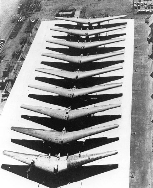
The RB-49 was intended as a reconnaissance bomber, where its inability to carry large nuclear weapons would not be a handicap. However, two months after awarding the contract, the USAF canceled it. It had become clear that other aircraft such as the Boeing B-47 Stratojet and the forthcoming Boeing B-52 Stratofortress would be able to handle this mission, so that a specialized aircraft was no longer necessary for the task. Nevertheless, one YRB-49 prototype was completed, and made its first flight in May 1950. Flight testing continued until April 1951. The prototype YRB-49 was scrapped in 1953, and all remaining YB-35/49 aircraft, in partial stages of conversion, were scrapped as well. Below they are shown lined up, waiting to be dismantled.
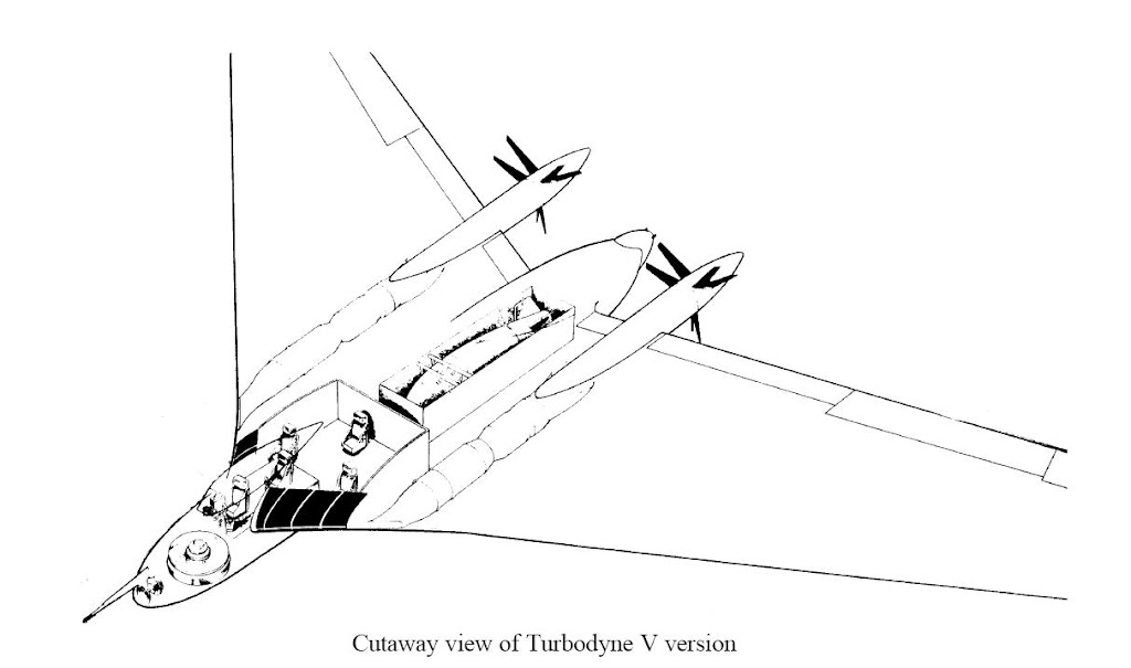
Northrop submitted several design studies for a new version of the flying wing, this time with a large enough bomb bay to accommodate the nuclear weapons of the day. One proposal would have been powered by two Northrop Turbodyne V turboprop engines, each producing 10,000 shaft horsepower, driving contra-rotating propellers. Its design sketches are shown below.
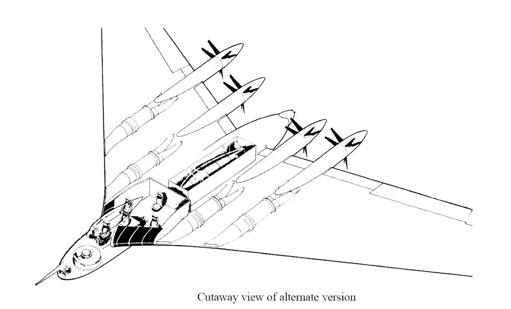
Another proposal would have substituted four smaller Allison turboprop engines for the two Northrop monster machines, also driving contra-rotating propellers, producing something like this:
However, by now the Convair B-36 and Boeing B-47 were in production, and the B-52 was on the horizon. The Air Force’s needs would be met for the foreseeable future, and there was no room for these proposals. The day of the ‘flying wing’ bomber appeared to be over.
It’s time now to turn back the clock a few years. I mentioned that the XB-35’s progress had been delayed, due in part to Jack Northrop taking people off that project to work on other ‘flying wing’ aircraft. Let’s take a brief look at those other planes.
The first was a proposal by Jack Northrop to build a rocket-powered fighter, similar in concept to the German Messerschmitt Me 163 Komet. It would utilize his ‘flying wing’ concept, although with a tail, which he promised would render it capable of exceptionally high speeds. The US Army Air Force liked the idea, and contracted with Northrop to produce three gliders to test the aerodynamic qualities of his proposal. In their unpowered version, they would be known as the MX-334.
The aircraft was built of non-vital materials, so as not to impact war production. The pilot lay on his stomach, chin supported in a V-shaped strut, so as to minimize the effect of G-forces during high-speed maneuvers.
The MX-334 made its first flight in October 1943, towed by a P-38 Lightning fighter.
Unpowered gliding flights continued until the first rocket-powered flight in July 1944. The testing was an ‘interesting’ experience for the pilots involved, as one source relates:
In the rather bland prose of official Army flight test reports, there is little evidence of the moments of stark terror experienced by company pilots Alex Papana and Harry Crosby at the controls of the tiny gliders.
Army pilots concluded that the glider was indeed flyable and controllable about all three axes. Aileron effectiveness was good, but fell short of current requirements for fighter aircraft. With regard to directional control, the time lag between operation of the rudder pedals and movement of the air-operated control surfaces was so great that the arrangement was considered impractical for that type of aircraft. Despite these limitations, the overall handling characteristics of the MX-334 were considered as good as or better than those of any other flying wing aircraft tested by the Army pilots to that date.
Test pilots sometimes described the tragedies and misfortunes that mark their daily lives in language entirely different from the engineering jargon of formal reports. Alex Papana and Harry Crosby flew many flights in the MX334 gliders that deserved a few extra superlatives in their description.
Two harrowing experiences occurred during this program. The first involved Alex Papana as pilot. Upon reaching the test altitude, Alex reached for the tow-line release, but inadvertently pulled the lever which jettisoned both the upper and lower escape hatch covers. The absence of the stream-lining effect of the hatch enclosures resulted in a dramatic increase in airplane drag and brought on very severe aircraft buffeting. Through a combination of pilot skill and good luck, Alex successfully landed on the lake bed after what must have been a hair-raising descent.
The other harrowing experience occurred a few days later with Harry Crosby as the pilot. Immediately following towline release, Harry flew into the propwash of the P-38 tow plane … his glider pitched up, stalled and rolled off into a spin from which it recovered in a stable, shallow glide. The problem, however, was that it was flying inverted, and there was Crosby on his back in a prone position aircraft and unable to reach the controls. The escape hatch, which normally was on the bottom of the airplane, was now overhead. Somehow Harry managed to jettison the hatch and crawl through the opening to the top of the wing, which really was the bottom of the wing. He sat there for a moment contemplating his predicament. After deciding there was nothing he could do, he released his grasp, slid off the wing, and deployed his parachute. When he looked around he was amazed to see his still up-sidedown glider flying in circles around him and descending at about the same rate he was. Although both the glider and the pilot landed at about the same time and in about the same place, they did not collide and Harry escaped without injury. The glider was damaged beyond repair.
Harry Crosby can be seen in this picture of an MX-334. He’s standing with his feet through the bottom hatch, and his body through the top hatch, which gives some idea of the very small size of these gliders!
In June 1944 an Aerojet rocket motor, developing 427 pounds of thrust, was installed in one of the remaining two gliders, which was re-designated the MX-224 to indicate that it had been equipped with an engine. Harry Crosby flew it the following month, the only pictorial record of his flight being this rather blurred and grainy photograph. The rocket exhaust can be seen behind the aircraft.
Testing continued for a few months, but the lack of a more powerful rocket motor, and the greater availability of the new jet engines, meant that the MX-334/324 design was now too limited. Jack Northrop had been hard at work on a new design, to take advantage of jet propulsion, and the prototype of the Northrop XP-79 was now nearing completion. The rocket program was wound down in anticipation of the new aircraft.
The XP-79, also known as the ‘Flying Ram’, was unusual for its day. It was again a ‘flying wing’ with tail surfaces, but constructed of welded magnesium alloy instead of aluminum. Like the MX-334, the pilot would lie prone inside the fuselage. It was originally intended to be rocket-powered, but it was adapted early on to use two Westinghouse J30 jet engines, each producing 1,200 pounds of thrust. It was nicknamed the ‘Flying Ram’ because for a while, there was serious discussion of using its extremely strong construction as an air-to-air combat weapon, its pilot deliberately ramming enemy aircraft to bring them down. As Jack Northrop said:
“It was designed as a projectile, with the thought that it could be used to intercept and knock wings or tails off other airplanes. Rather than shooting at them, this airplane was going to slice sections off the other airplanes to destroy them.”
This proposal was never taken further . . . largely because senior US officers pointed out that if they ordered their pilots to ram enemy planes, the answers they received were likely to be rather short, not at all polite, and very much to the point!
The XP-79 was ready to fly in September 1945, only the fourth US jet aircraft to take wing. Tragically, its first flight was also its last. Fifteen minutes into the flight, Harry Crosby lost control, and the aircraft went into a spin. Crosby attempted to bail out, but was struck by the aircraft. He was unable to open his parachute, probably because he was either knocked unconscious by the impact or too severely injured to reach the ripcord. His body was recovered near the wreckage of the aircraft.
With the loss of the only prototype, and the end of World War II, the urgency had gone out of the program, and the ‘flying wing fighter’ project was abandoned.
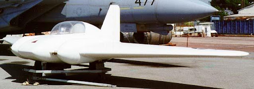
Another ‘flying wing’ project undertaken by Northrop in World War II, at the same time as the MX-334 program, was to develop a ‘flying bomb’ along the lines of the German Fieseler Fi 103 (better known as the V-1). He developed two versions, one to be flown by a human pilot to verify its handling and aerodynamic qualities, the second to be unmanned, powered by jet engines. Both would be known as the JB-1. The central fuselage would contain the engines, with two containers, one on either side, containing explosives. The whole affair looked rather like a fat bat, and as a result came to be known as the ‘Bat Bomb’.
The glider version was tested in 1944, again by Harry Crosby, with success. The prototype is preserved today at the Western Air Museum in California.
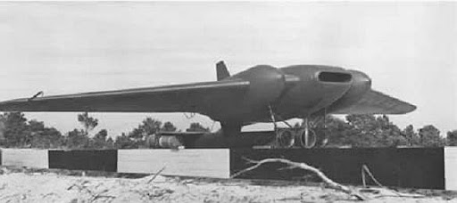
The jet-powered bomb version of the JB-1, shown below, was first tested in December 1944.
The prototype crashed after its launch from a rocket-powered sled on a ramp, because the elevon setting was incorrect. The two General Electric B1 turbojets, each developing only 400 pounds of thrust, also proved unreliable, causing further problems. As a result, the program was switched to pulse-jet propulsion, using a Ford PJ31 engine developed on the basis of what had been learned from the German V-1 program. The new missile, shown below, was designated the JB-10.
It was intended to fly for up to 200 miles, directed by a pre-programmed guidance system, and crash onto its target. It carried two 2,000-pound high-explosive warheads, one on each side of the central fuselage containing the pulse-jet engine. It was first launched in April 1945, but its engine proved unreliable once more. Of ten test firings, eight failed, and the remaining two were only partial successes. With the end of World War II, the urgent need for this and similar weapons had passed, so the program was canceled in January 1946.
With the end of these weapons programs, followed by the demise of the XB-35 and YB-49 programs by the early 1950’s, it seemed that the days of the ‘flying wing’ were over. However, advances in materials and technology paved the way for new interest in the ‘flying wing’, particularly because it was a naturally ‘stealthy’ design, with minimal radar reflection. When Northrop began to design what would become the B-2 Spirit bomber in the late 1970’s, they initially used a diamond shape for their aircraft: but when the USAF optimized their requirement around low-level penetration, the Northrop designers went back to the drawing-board and came up with a new and ultra-modern flying wing design. To the amazement of many, the current B-2 Spirit and the YB-49 have precisely the same wingspan (192 feet)!
Jack Northrop retired from his company in 1952, although he remained ‘on the books’ as a consultant, helping to develop the T-38 Talon supersonic trainer, and from it the F-5A/B Freedom Fighter and F-5E/F Tiger II fighter-bombers. After the death of his wife in 1977, he suffered a series of strokes, and became progressively weaker. However, he was well enough to be brought back to the company he founded, for a very special occasion.
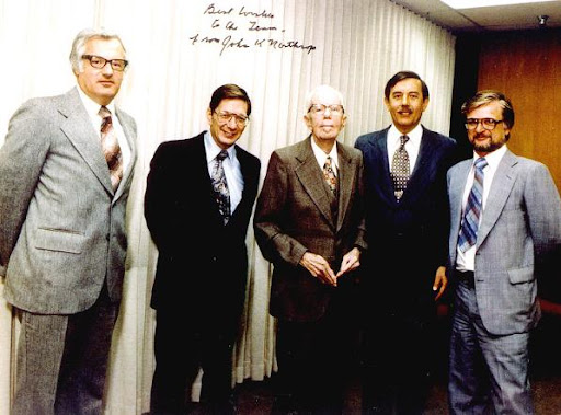
The team designing the B-2 Spirit obtained special security clearance to show their design to Jack Northrop, the man who had essentially invented the big-bomber flying wing. He was brought to the plant in 1980, and shown drawings and a scale model of what they proposed to build. It was apparently a very emotional moment for all concerned, and Northrop supposedly quipped that this must be why God had kept him alive for the past twenty years! He’s shown below (center) with the heads of the B-2 design team.
Jack Northrop died in his sleep on February 18, 1981. He did not live to see the culmination of his ‘flying wing’ bomber, the B-2 Spirit, make its first public flight on July 17th, 1989.
Nevertheless, his influence in its design is clear: and that same influence, plus what’s been learned from the B-2, plus new advances in technology, are driving a whole new wave of aircraft developments, with Northrop Grumman firmly at the head of the field.
We’ll talk about them in the next few weeks.
Peter
















I actually saw a YB-49 landing at Lake Charles AFB (later renamed Chennault AFB) when I was very young.
MC
OUTSTANDING post Peter! A great recap of the flying wing concept and evolution!
So I wonder how much help he got from studying the work of the Hortens?
Tim, as far as I know, Northrop never did study their work. The first Horten glider flew several years after Northrop’s first ‘flying wing’ powered aircraft, and of course, during the war years, there was no contact at all. I doubt very much whether the Hortens’ work was known to Jack Northrop at all.
Same goes for the B-2 Spirit, decades later. Some German conspiracy theorist types have tried to maintain that Northrop got the idea for the B-2 from studying a captured Horten aircraft in a US museum. It’s total nonsense, of course. The amount of mathematical calculation and stealth research used to determine the B-2’s shape and size were mind-boggling in their size and complexity. There’s simply no way a primitive World War II design could possibly have given them the inspiration.
But the story starts even earlier with the work of John William Dunne and the ‘Blair Atholl’ school (one of whose products at least the US Army bought, during the Great War) and Prof Geoffrey Hill’s Pterodactyls for the Westland Aircraft Company.
Anonymous, you’re right: but those are outside the scope of this article. This deals specifically with Jack Northrop’s flying wing designs – the most complete and successful prior to the B-2 Spirit bomber. If I’d tried to cover all the less successful entrants to the field, the article would be ten times as long!
Those wishing to read more about ‘flying wings’ all over the world may see this site:
http://tinyurl.com/cgevpk
Lots of useful information there.
“Of course, this was due to the conventional ailerons and rudders,”
Elevators and rudders are on the empennage; ailerons are (usually) on the wings.
Axis control surface
roll ailerons
pitch elevators
yaw rudder(s)
Many thanks, Peter. After all the posts/sites I’ve seen lately about the Hortens being the grandfathers of the flying wing, you give credit where it is due. Still I wonder: Is this not one of those ideas, whose time has come, so that sketches and prototypes start popping up everywhere around the same time?
Comments, anyone?
Peter,
When Jack was elderly, he asked Clete Roberts of the Los Angeles PBS station KCET to interview him so he could set the record straight on the (non)developemnt of the design. He was not happy about taking the reason for the government destruction of the planes to his grave, and said as much.
Has anybody any information about the Flying Wings being evaluated in England. When I was young we spent our summers on the south coast from 1947 right through to the 1960s and there was a lot of experimental flying going on there because we were just west of the measured mile which was along the coast near Bognor Regis. This was used for many attempts at breaking the air speeds records. I believe that many of these aircraft were flown from RAF Tangmere or Ford which was a Naval Air Service base. The Royal Aircraft Establishment, Farnborough had an outpost there and one summer there was some extensive flying of the flying wings. For the day they were huge and there were both the propeller driven version and the jet versions flying. The propellor version had a very distinct noise and we could hear it take off from the airfield which several miles away. I assume the RAE trialed it with a view to the RAF using it as a bomber. However, I have never seen any records of them having been in the UK. Does anyone have any information on this.
Great article! I'll have to show this page to my aunt/godmother because she is one of Northrop's grandkids. I'm sure they'll appreciate it too
Military Ch. just had this story on 6/25/12. Interviews with the designers of the B-2. One of the test pilots is still alive, and he was in the piece,too. Where did Jack go to college? He was a JERSEYITE, but grew up in Santa Barbara.
The N9MB at Planes of Fame is in flying shape and was flown in there last air show. http://planesoffame.org/index.php?mact=staircraft,cntnt01,default,0&cntnt01what=stplanes&cntnt01alias=N9MB&cntnt01returnid=128
The flying wing is the pyramid of aerostructures. It looks pretty but it's internal volumetrics and high aspect ratio makes it essentially limited in it's payload/performance range to a very narrow kinematic profile.
Short chord means low pitch authority which in turn means if you ever get alpha beyond a certain point, it's going to flip because the nose won't go back down as the surfaces blank. This is often structurally unsustainable.
In yaw, differential lift due to spanwise loading of heavy mission payloads from the centerline outwards often leads to wing droop when munitions are released differentially and the difference in lift coefficient resulting from this pulls the nose around into a crab whose imposed sideslip becomes worse as you apply yoke to bring the wing back up.
The same is true for fuel which must be carefully maintained, squared balanced, not only for flying qualities but to avoid excessive stress on the outer panels.
A tube+wings approach, which nominally much less efficient overall, provides the option to move the airfoil up and down the fuselage with adjustments to span and sweep for aspect ratio and lift being compensated for at 'just one end' in the size of the tail.
This allows the Eagle-Carries-Rabbit approach to suspending the main fuselage beneath thick large centerline spars rather than a structural box web (spars at either end with stringers inbetween which must become stiffer as the span increases and they get thinner, eating volume. CG margins are wider, moment arms are longer and drag is reduced at anything over 400KTAS because the sectional thickness of a man-rated airfoil is actually much larger in it's presented frontal cross section than the narrow area of the cockpit/cabin.
Anyone who has ever been stuffed into the sausage casing of a modern jet airliner can feel free to cuss the morons who decided that an MD-80, B737 or EMB-145 was a great solution to the mid-range air transportation needs of this country. But compare it to this-
Northrop's Airliner
https://www.youtube.com/watch?v=ub6U9CL0K_A
And they at least make sense for their volume usage. Eighty passengers in a 53X30 foot center section of a jet the size of a 747 both steals volume from the fuel and engines and allocates far too little to paying passenger loads. This inability to enclose useful volume in a thin enough section is the real problem of the Flying Wing design as a whole and passenger versions specifically.
If it is standardized on the LRSB as a followon subsonic bomber in the class of B-2, you will be able to add inadequate speed and questionable bombload as well.
Jack Northrop was an interesting man but his designs were technically flawed then and remain very large compromises today.
Blended Wing Bodies and Modified Deltoid airframes are the way forwards because they mass and volume load along the longitudinal centerline rather than transversely, over the span.