On December 3rd, 2010, the Royal Australian Air Force (RAAF) will officially retire its remaining General Dynamics F-111 Aardvark strike aircraft. The date will mark the end of more than four decades of service for this remarkable plane.
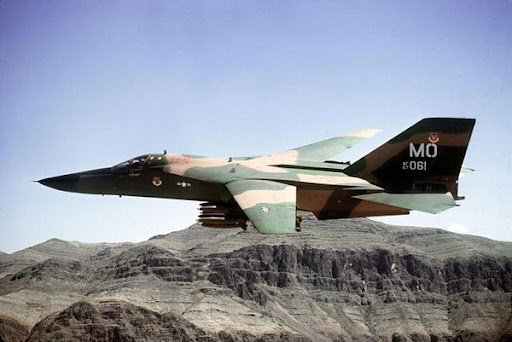
The F-111’s story is so complex that we can’t possibly do it justice in a single Weekend Wings article. I’ll therefore break the story into two parts. This article will examine the genesis of the program, and focus on the new and complex technologies that went into it. The second instalment, next weekend, will discuss the aircraft’s development and operational career, and the numerous variants that were produced.
The F-111 was perhaps the most unfortunate and problem-plagued aircraft program since World War II. It was conceived at a nexus in military-industrial development, a ‘sea change’ from old ways and technologies to new. The story of its genesis is one of industrial trench warfare, slogging away at almost intractable obstacles. Its operational debut was marred by the effects of these problems, and it would be many years before it became an effective aircraft. However, despite all these issues, the F-111’s story is ultimately one of triumph over adversity.
One factor affecting the F-111 program was the growing cost of modern aircraft. Earlier planes had usually been designed to fulfill a single function or purpose. This had simplified their design, as they didn’t have to take multiple roles into account, and they could be oriented towards a specific mission and built to suit its demands and requirements. However, the ever-increasing cost of aircraft was beginning to restrict this approach. Financial reality dictated that new aircraft designs should be capable of performing as many different roles and missions as possible. It would cost an air force a lot less to buy, say, three types of aircraft that could handle nine or ten different missions, than it would to buy nine or ten purpose-built designs, one for each mission. Not only would all the research and development costs of the latter programs be saved, but training, maintenance and other operational requirements would be greatly simplified and rationalized, saving even more money. Furthermore, mass production would lower the cost per individual airframe.
In the USA, this concept was taken a step further with the appointment of Robert McNamara as Secretary of Defense in the Kennedy administration in 1961. He came from a corporate management background, with a strong emphasis on management systems and integration of operations. He recognized that air operations were carried out by the US Air Force, the US Navy and the US Marine Corps. This offered opportunities for synergy. Why could an aircraft not be designed to meet the needs of more than one service, thereby taking economies of scale to the next level? This had never been attempted before, and indeed was actively opposed by many military leaders because of their ingrained ‘not invented here‘ cultural perspective. This opposition was aggravated by competition between the services for their share of the overall defense budget, and by inter-service conflict over who would be in charge of high-prestige national programs such as the nuclear deterrent, or specific missions such as amphibious assault.
Another problem was the simultaneous evolution of new levels of performance and capability in several technologies; electronics, engines, metallurgy and aircraft design. Each had been ‘pushing the envelope’ since World War II, and considerable progress had been made. However, technology incorporated into a production aircraft is usually at a stable level, where it is understood and can be readily supported. By contrast, the F-111 demanded such high performance in so many areas that older, more stable technologies simply would not suffice. Instead, ‘cutting-edge’ technology – untried, untested, in many cases not even ready for production – from all of the disciplines mentioned above had to be integrated into a single airframe. This was to cause enormous problems. A number of USAF personnel were to be killed and injured because of shortcomings in the F-111 that were directly attributable to so much new technology being shoehorned into it without adequate opportunity for debugging or operational testing. The ‘cutting edge’ of technology became, all too literally, the ‘bleeding edge’ in this program.
These technological problems were intensified by McNamara’s insistence on a greatly speeded-up development process. Coming from the commercial world, he applied business management principles to military systems development. This could be, and was, beneficial in many ways: but no commercial system of the time even approached the complexity of the F-111 program. McNamara wanted development to run in parallel with early production of the F-111. Lessons learned from testing were to be incorporated into the first production aircraft at a later date if necessary. Indeed, much of the testing normally done in development would, in practice, be done by the first units to operate the aircraft. This might have worked with a less complex plane, but it proved disastrous with the F-111. More than a decade of operational service was to pass, and lives would be unnecessarily lost, before all of the major problems it experienced had been ‘ironed out’.
Let’s begin by examining the history behind the F-111. How and why was it conceived? What led to its development?
In the late 1950’s the USAF’s strike aircraft fell under the aegis of Tactical Air Command.

It had developed the Composite Air Strike Force concept following the Korean War. This envisaged the deployment of strike (i.e. interdiction and close air support) and fighter aircraft, complete with troop carrier, transport, reconnaissance and air-to-air refueling tanker units, to trouble spots throughout the world. TAC had begun to accept the famous ‘Century series‘ of combat aircraft into service, but was experiencing all the problems associated with their brand-new technology, which was not yet mature and frequently proved unserviceable.
TAC was also developing a tactical nuclear strike doctrine. Early nuclear weapons were large, heavy and cumbersome, requiring a large aircraft to deliver them. However, by the late 1950’s newer, smaller, lighter versions were being deployed. These could be carried by tactical aircraft, and their lower yields meant they could safely be used against targets in closer proximity to friendly forces, or against areas through which friendly forces might be expected to move in the short term. TAC wanted a more reliable low-level strike aircraft for this purpose, able to hit targets with pin-point precision. It should preferably have greater bomb-carrying capacity than the Century series, plus the ability to deploy over long distances at high speeds to trouble spots.
To meet TAC’s needs, in June 1960 the USAF issued Specific Operational Requirement number 183 (SOR-183). It required an attack aircraft capable of speeds of Mach 2.5 at altitude and Mach 1.2 at low level. It was to be capable of operating from short, unprepared airfields, with runways as short as 3,000 feet. It was to have a low-level operational radius of not less than 800 miles (including at least 400 miles actually at low level, plus higher-altitude transit flight), and a ferry range (i.e. without weapons, but with full fuel) sufficient to cross the Atlantic Ocean. It had to lift between 15,000 and 30,000 pounds of payload, with a minimum of 1,000 pounds to be carried in an internal bomb bay. In order to meet these requirements, the USAF considered that variable geometry wings and a turbofan engine would probably be required. (More about both of these technologies later.) The project was labeled Tactical Fighter Experimental, or TFX.
The US Navy had something completely different on its mind. During the 1950’s it became increasingly preoccupied with the difficulties of defending its aircraft-carriers and their task groups against enemy air attack. The advent of high-speed jet-powered strike aircraft meant that they could close with the fleet much faster than during previous conflicts. The limited detection range of contemporary shipboard radars meant that there would be much less time available to intercept such threats. For example, given an effective radar range of 100 miles, an aircraft traveling at Mach 2 would need less than 5 minutes from initial detection to reach the carrier. Defending aircraft could not possibly be prepared, launched, and directed to intercept the enemy in so short a time. Furthermore, the advent of anti-ship guided missiles meant that attacking aircraft no longer needed to actually reach the carrier – they only had to get within missile range of it. This meant that even less reaction time was available to defend against such threats.
In response, the Navy decided to develop a complete system of fleet defense. It would have a long-range airborne radar component, to detect attackers at the furthest possible range: this became operational in 1964 as the Grumman E-2 Hawkeye early warning aircraft. This was originally intended to pass interception information to fighters armed with the proposed Bendix AAM-N-10 Eagle long-range air-to-air missile, which was to have a range of over 100 miles at a speed of up to Mach 4.5, and be capable of operating at altitudes up to 100,000 feet. To guide the missiles, the launching aircraft was to carry the proposed AN/APQ-81 pulse doppler radar system.
There were serious disagreements within the Navy as to what sort of aircraft was needed to carry the radar and missiles. To cut a long story short, it was initially decided that the aircraft would be no more than a launching platform for the missiles. It would not need to be highly maneuverable for dogfighting, and would not carry cannon, but would have to be able to loiter on combat patrol for extended periods at great distances from its parent carrier. This meant using economical engines at subsonic speeds to minimize fuel consumption. Side-by-side seating was preferred for the pilot and co-pilot, allowing them to share a single large radar display unit.
Douglas Aircraft Company began development of the F-6D Missileer to meet this requirement.
This aircraft would have been very large in comparison to its carrier-based contemporaries, weighing up to 60,000 pounds, with a crew of 3. However, early in its development serious doubts were raised within the Navy about its suitability. Opponents argued that once it had fired its missiles, the Missileer would be utterly defenseless, having to return to the carrier to rearm. While doing so, its low speed and poor maneuverability would render it highly vulnerable to enemy fighters. These arguments proved persuasive, and led to the Missileer program being canceled in December 1960. (However, its radar and missiles would continue in development, and emerge after many iterations as the AN/AWG-9 radar and AIM-54 Phoenix missile, both of which entered US Navy service aboard the Grumman F-14 Tomcat fighter in the 1970’s.)
The Navy issued a revised requirement for its long-range fleet defense fighter. It now wanted supersonic capability and greater maneuverability, but retained the need to loiter on combat air patrol for extended periods at long distances from the parent carrier. Only a large, heavy aircraft would be able to combine all these attributes. The Navy had experimented unsuccessfully with variable geometry wings (of which more later) during the 1950’s, but advances since those experiments had made the technology more viable. It offered a means of increasing payload and reducing landing speed (very important for carrier-based aircraft) without compromising combat performance. It was therefore specified as a likely solution to the new requirement.
So, by early 1961 there were two requirements on the table, one from the USAF and one from the USN. Both called for large, long-range, high-performance aircraft. The new Secretary of Defense, Robert McNamara, recognized a high-profile opportunity to apply the business management principles he wanted to implement across the Department of Defense and in all the armed services. He seized it. On February 14th, 1961, he ordered the USAF and USN to examine the possibility of uniting their differing specifications so that a single aircraft could satisfy both of them, thereby avoiding duplication of effort and saving a considerable amount of money.
Initial consultations between the two services led to agreement on the need for twin engines, variable geometry wings, and two crew members. However, their requirements for aerodynamic stress limits, top speed and physical size of the aircraft differed substantially. Nevertheless, in June that year McNamara ordered the two services to attempt to develop the TFX specification into an aircraft that could meet both services’ needs. By September McNamara had decided to proceed on the basis of the USAF’s requirements (which were the most complex and demanding), and adapt the resulting aircraft to meet the USN’s needs as well.
In October 1961 a Request for Proposals was circulated to the US aerospace industry. By December initial responses had been received from Boeing, General Dynamics, Lockheed, McDonnell, North American and Republic. None of the preliminary proposals were deemed acceptable, but Boeing and General Dynamics were asked to prepare more detailed submissions. They did so by April 1962. The revised proposals were still not satisfactory to all parties, and two more rounds of submissions followed, until later that year a selection board picked Boeing’s proposal for further development. However, McNamara overrode the board’s choice, on the grounds that the General Dynamics submission offered greater commonality between the proposed USAF and USN versions of the plane, thereby offering (at least in theory) better economies of scale. His action caused controversy, including a Congressional inquiry, but he was able to enforce his choice. General Dynamics signed a development contract for the TFX program in December 1962.
It can’t have taken long before the management team at General Dynamics must have wondered whether signing the TFX contract had been a wise decision. There were many new technologies involved in TFX, all of which had to be developed to production status and prepared for operational use in parallel with each other. It wasn’t possible to develop one technology, test and approve it, and then go on to the next one. The complexity of so many new and untested elements being developed simultaneously was to prove extraordinarily difficult, and would continue to cause problems for the F-111 in operational service for many years. To make matters worse, the project was to be developed as a matter of urgency, with aircraft being put into production before all the problems encountered in development had been fully tested and resolved. This factor, more than any other, was to prove a recipe for disaster.
Five new technologies caused the greatest difficulties. They were:
- Variable geometry wings incorporating high lift devices;
- Turbofan powerplants and associated systems and structures;
- The need for new metal alloys;
- A sophisticated, automated navigation and weapons delivery system; and
- A novel crew escape system.
The remainder of this article will examine each of these technologies in turn.
VARIABLE GEOMETRY WINGS.
Variable geometry wings, or ‘swing-wings’ as they’re sometimes called, were first conceived by Messerschmitt AG in Nazi Germany. In July 1944 the company responded to the Emergency Fighter Program with a revised version of its P.1101 project, initial design of which had begun as early as 1942. It included an adjustable wing whose angle of sweep could be altered on the ground before flight. A prototype was constructed, but did not fly before the end of World War II, when it was captured in an incomplete and damaged state by US forces.
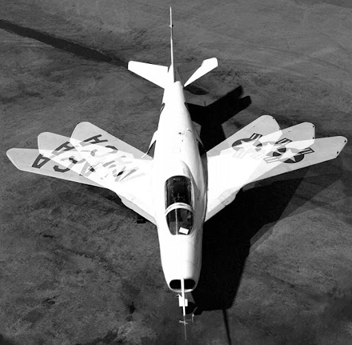
The P.1101 prototype was brought to the USA and delivered to the Bell Aircraft Company for analysis. There it inspired chief designer Robert J. Wood to develop the Bell X-5 experimental aircraft. It was visually similar to the Messerschmitt P.1101, but incorporated a mechanism to change the angle of the wings in flight, rather than requiring them to be manually adjusted on the ground.
The X-5 first flew in 1951. It proved very difficult to control, not least because as the wings were swept further back, the lift vector they generated also moved, making the aircraft unstable. It also had vicious spin characteristics, which were to lead to the loss of one X-5 in October 1953, killing the test pilot, USAF Major Raymond Popson.
The surviving prototype was not further developed, due to the limitations of technology at the time, but the X-5 program provided valuable initial insight into the challenges of flight with a variable geometry wing. It holds an honored place in aviation history as the first aircraft to fly with this technology. The surviving X-5 aircraft is in the USAF Museum in Dayton, Ohio.
The US Navy was also interested in the use of variable geometry wings for its carrier aircraft. The technology held out particular promise for such an environment as aircraft grew larger and heavier. They needed larger wings, to reduce their wing loading to an acceptable level: but larger wings were a problem in terms of hangar and maneuvering room on board an aircraft carrier. Wings that could be swept back to take up as little space as possible offered a real advantage. In addition, when fully extended they offered slower landing speeds and better low-speed handling, always desirable for carrier operations, whereas in the fully swept position they offered the prospect of good high-speed performance.
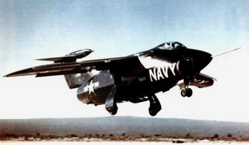
Grumman developed the XF10F Jaguar for the Navy to investigate swing-wing technology.
It first flew in 1952, almost a year after the Bell X-5. Its wings could sweep in flight from 13½° to 42½°, less than the X-5, but adequate for the XF10F’s rather sluggish performance (caused by having to fit a lower-powered engine than that for which it had been designed).
As with the X-5, serious stability and control problems were encountered, leading the Navy to terminate the XF10F project in April 1953 with only a single example built. Sadly, it hasn’t survived.
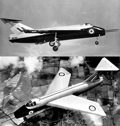
Another experiment with variable geometry wings took place in Britain at about the same time. Short Brothers developed the SB5 in response to Air Ministry requirement ER.100.
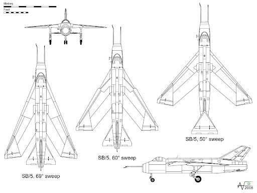
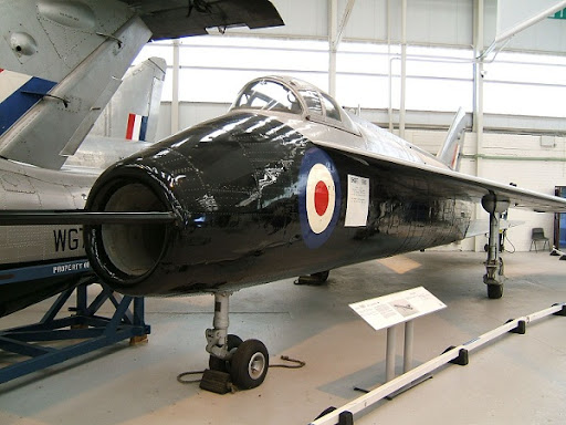
The SB5 was more akin to the Messerschmitt P.1101 than to the Bell X-5 or Grumman XF10F. It was designed to test different wing sweep angles for a forthcoming proof-of-concept fighter prototype, the English Electric P1A. Its wing couldn’t be moved in flight, but could be adjusted on the ground to 50°, 60° or 69° of sweep. Since testing the wing was its only reason for existence, other aspects of the SB5’s design were relatively primitive – deliberately so, to save money. It didn’t even have a retractable undercarriage!
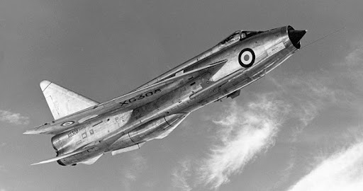
The rear fuselage was detachable. Two were built, one with the tailplane above the fin and one with it below, to test which was the most efficient configuration. The SB5 first flew in December 1952. Experience gained with it provided the information designers needed to proceed with the P1A prototype, which in turn evolved into the English Electric Lightning fighter.
Happily for aviation enthusiasts, the SB5 survived its test program. It may be seen today in the RAF Museum, complete with both tail assemblies. In the in-flight photographs above, the upper-tailplane fuselage is shown; as displayed in the museum, below, the lower-tailplane fuselage is attached. (The latter configuration proved most efficient, and was subsequently used on the P1A and the Lightning.) The upper-tailplane unit may be seen next to the aircraft’s nose.
Thus, by the mid-1950’s, the viability of variable geometry wings had been proven in theory: but the handling of the aircraft using this technology had been so difficult as to render it useless for practical purposes. The reason wasn’t hard to find, as examination of the photographs and line drawings above will show. As the wing’s angle of sweep was increased, the portion of the wing nearest the aircraft body had to retract into the fuselage, thereby decreasing the overall wing area. This also had the effect of moving the center of the remaining lifting surface – the center of balance, if you will – further out, down the wing. If the aircraft’s controls and trim were set up for the wing at one angle, they proved inadequate – sometimes dangerously so – when this was changed. The contemporary understanding of aerodynamics and control systems was not sufficiently advanced to find a solution to this problem.
The technology was not further developed until 1959, when researchers at NASA came up with a revolutionary idea. Instead of pivoting the ‘swing-wing’ at a single point, they suggested a double pivot, so that the wing root could move in and out as well as angle forward and back. This necessitated the use of a wide ‘shoulder’ joint in the fuselage, which kept the moving parts of the wing further away from the fuselage. Since it no longer had to retract into the latter, more of the wing’s lifting surface or area was preserved at any given angle of sweep. The ‘shoulder’ could also be shaped as an airfoil, providing additional lift, and could conceivably support weapons pylons, thereby taking at least some of that burden off the wings themselves. The ‘shoulder’ concept is clearly illustrated below in this line drawing and photograph of the F-14 Tomcat fighter. Note how little of the wing area is obscured by the fuselage or ‘shoulder’ as its angle changes. Almost all of its lifting surface remains usable.
This new approach held out the promise of greatly improved handling for variable geometry aircraft, and was adopted for the F-111. However, note that the F-111’s ‘shoulder’, shown below, is not as broad or pronounced as it is on the later F-14, shown above.
The concept of the ‘shoulder’ (also known as the ‘glove’) was not yet fully developed, and the designers at General Dynamics didn’t make it sufficiently large or aerodynamically efficient. This was to plague the F-111 all its life (although designers of subsequent swing-wing aircraft [such as the F-14, shown above] would learn from this early mistake and avoid it). In particular, its performance in supersonic flight was initially unacceptably poor.
On December 19, 1962, representatives of General Dynamics and Grumman visited NASA Langley for discussions of the supersonic performance of the F-111. The manufacturers were informed that the supersonic trim drag of the aircraft could be significantly reduced and maneuverability increased by selecting a more favorable outboard wing-pivot location. Unfortunately, the manufacturers did not act on this recommendation, and it was subsequently widely recognized that the F-111 wing pivots were too far inboard. (It should be noted that the F-14 designers, aware of this shortcoming, designed the F-14 with a more outboard pivot location.) The F-111 subsequently exhibited very high levels of trim drag at supersonic speeds during its operational lifetime.
Incremental steps were taken to improve the situation, although they didn’t completely cure the problem. (In fairness, let’s remember that the F-111 was the first service aircraft to use variable geometry. It represented the state of the art at the time, so inevitably its designers had more to learn, and made more mistakes, than those who followed them.) The engineers at NASA Langley were to play a very important part in solving the F-111’s aerodynamic problems.
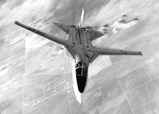
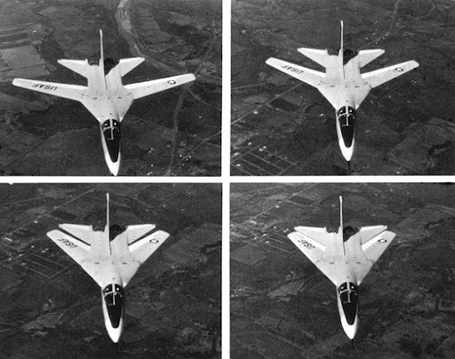
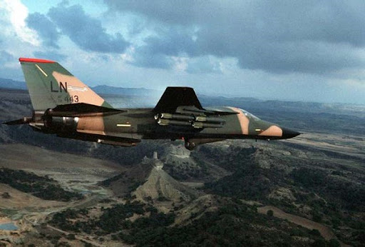
The F-111’s wings were long and thin. They could sweep from 16° (fully forward) to 72½° (fully back), as shown in this series of photographs of the F-111A, the first production model.
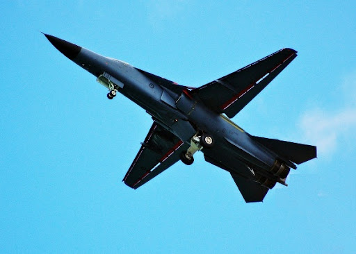
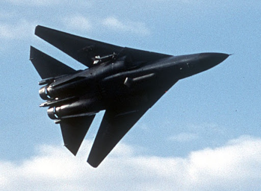
The wings were designed to flex under the g-forces imparted by heavy loads and high-speed maneuvers (when fully forward, the wingtips could displace from their position of rest by almost 7 feet under their designed maximum load of 7.33 positive g). The photograph below, showing a RAAF F-111 demonstrating a high-g turn at an air show, shows clearly how the wings bend under the aerodynamic stresses involved.
The stress of constant flexing was to lead to metallurgical problems, of which more later. To reduce wing loading for improved low-speed handling, full-length double-slotted flaps were provided, as well as full-length leading edge slats. Flaps and slats together greatly increased the wing area, as can be seen in the photographs below.
In addition, spoilers rose from the top of the wing to interrupt the airflow and assist with deceleration after landing. They are visible above the wing in the photograph below.
A set of pivoted surfaces were provided on the wing ‘shoulder’ or ‘glove’. They were normally flush with the wing, but at slow speed, when maximum lift was required, they could be extended to smooth the airflow over the ‘shoulder’ and around the leading-edge slats. This helped to reduce the drag caused by the less-than-fully-efficient ‘shoulder’ design, as described above. They are shown below, circled in red.
The tailplane or horizontal stabilizer was set at the same height as the wing, so that when the latter was fully folded to the rear, wing and tailplane together formed the shape of a large delta wing, as shown below. This offered aerodynamic advantages.
The tailplane did not have an attached elevator: instead, the entire tailplane moved, forming an ultra-large control surface for the roll (i.e. longitudinal) and pitch (i.e. lateral) axes of rotation. The movement of the tailplane is clearly illustrated in this photograph of the tail of an RAAF F-111C, below.
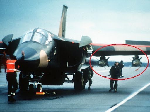
The wings would carry most of the weapons, as the fuselage’s internal bomb bay was small. Four pylons were fitted to each wing, each with a load capacity of up to 5,000 pounds. They could carry weapons or auxiliary fuel tanks. The two inboard pylons on each wing (closest to the fuselage) could swivel to keep their load aligned with the fuselage as the wings swept forward or back, thereby minimizing aerodynamic drag. Each could carry a single large or multiple smaller weapons such as bombs, missiles and rockets.
The two outermost pylons on each wing could not swivel. They were set up to be aligned with the fuselage when the wings were swept forward – i.e. for low-speed flight. For this reason, they were usually reserved for auxiliary fuel tanks. After takeoff, the aircraft would fly at lower speed with its wings swept forward while the fuel in these tanks was consumed. When they were empty, the tanks would be dropped, following which the wings could be swept to any desired angle, depending on the aircraft’s speed.
The F-111’s normal combat radius, using internal fuel only, was about 1,000 miles, or about 1,300 miles with two external tanks, as shown above. For very-long-range missions, all of the wing pylons could be used for fuel tanks, carrying only a small weapons load in the internal bomb bay. The F-111’s maximum range (in ferry mode, without weapons, carrying external tanks plus more fuel in the weapons bay) could be stretched as far as 4,200 miles, allowing trans-oceanic deployments. In-flight refueling could extend the range even further, of course.
In order to reduce the wing loading and improve low-speed handling for the purposes of carrier landing, larger wings were designed for the US Navy version of the F-111. That version was canceled (as we’ll discuss later), but its larger wings were adopted for a bomber version of the F-111 for the USAF’s Strategic Air Command, and subsequently used on other models, providing additional fuel capacity and improved maneuverability.
The F-111’s wings were technically very complex for its time, difficult to design and manufacture. The ‘state of the art’ had to be significantly improved in order to make them work. The F-111 was the ‘guinea-pig’ in this endeavor, and while its wings were never as good as they could have been with the benefit of later advances in technology, those advances were to a large extent the fruit of experience gained with this program.
TURBOFAN POWERPLANTS AND SYSTEMS
The first jet engines were so-called turbojets.
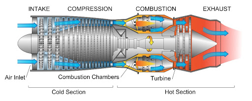
Turbojets consist of an air inlet, an air compressor, a combustion chamber, a gas turbine (that drives the air compressor) and a nozzle. The air is compressed into the chamber, heated and expanded by the fuel combustion and then allowed to expand out through the turbine into the nozzle where it is accelerated to high speed to provide propulsion.
Turbojet engine (click diagram for a larger view). Image courtesy of Wikipedia
Turbojets offered excellent high-speed, high-altitude performance compared to piston engines, but had several shortcomings. They were very ‘thirsty’, consuming large quantities of fuel in relation to the distance covered. Early turbojets were also notoriously slow to respond to throttle input, so that a change in power might take several seconds between the engine controls being adjusted and the power actually being delivered. This caused more than a few accidents at low altitude.
The high fuel consumption of turbojet engines was of concern to both military and civilian aviation. If a more economical jet engine could be developed, flights over longer ranges could be undertaken. To achieve this, the turbojet engine was developed into what became known as the turbofan. Wikipedia describes the evolution as follows:
In a single-spool (or single-shaft) turbojet, which is the most basic form and the earliest type of turbojet to be developed, air enters an intake before being compressed to a higher pressure by a rotating (fan-like) compressor. The compressed air passes on to a combustor, where it is mixed with a fuel (e.g. kerosene) and ignited. The hot combustion gases then enter a windmill-like turbine, where power is extracted to drive the compressor. Although the expansion process in the turbine reduces the gas pressure (and temperature) somewhat, the remaining energy and pressure is employed to provide a high-velocity jet by passing the gas through a propelling nozzle. This process produces a net thrust opposite in direction to that of the jet flow.
After World War II, 2-spool (or 2-shaft) turbojets were developed to make it easier to throttle back compression systems with a high design overall pressure ratio (i.e., combustor inlet pressure/intake delivery pressure). Adopting the 2-spool arrangement enables the compression system to be split in two, with a Low Pressure (LP) Compressor supercharging a High Pressure (HP) Compressor. Each compressor is mounted on a separate (co-axial) shaft, driven by its own turbine (i.e. HP Turbine and LP Turbine). Otherwise a 2-spool turbojet is much like a single-spool engine.
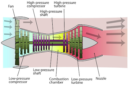
Modern turbofans evolved from the 2-spool axial-flow turbojet engine, essentially by increasing the relative size of the Low Pressure (LP) Compressor to the point where some (if not most) of the air exiting the unit actually bypasses the core (or gas-generator) stream, passing through the main combustor. This bypass air either expands through a separate propelling nozzle, or is mixed with the hot gases leaving the Low Pressure (LP) Turbine, before expanding through a Mixed Stream Propelling Nozzle. … Turbofans also have a better thermal efficiency. … In a turbofan, the LP Compressor is often called a fan. Civil-aviation turbofans usually have a single fan stage, whereas most military-aviation turbofans (e.g. combat and trainer aircraft applications) have multi-stage fans.
Turbofan engine (click diagram for a larger view). Image courtesy of Wikipedia
Rolls-Royce in England was the first company to produce a turbofan engine, which they christened the Conway. Other companies followed suit. Early turbofans showed promise, giving better fuel consumption, better throttle response, and proving to be less maintenance-intensive than contemporary turbojets.
However, applying turbofan technology to military aircraft posed a host of problems. Air intake geometry for turbojets was well understood by the late 1950’s, but the low-pressure bypass systems of early turbofan engines would require a new approach, which was not fully understood at first. Furthermore, the engines would have to function at widely varying extremes of operation, from low-level to high altitudes; from low speeds to high supersonic dashes; and at extreme angles of attack. The demands on military turbofans would be far greater and more complex than on their commercial equivalents. However, their greater fuel efficiency meant that their adoption was inevitable. So it proved for the F-111.
Pratt & Whitney won the competition to design the F-111’s engines. They had begun development of a low-bypass turbofan for the Navy’s proposed subsonic F-6D Missileer aircraft, which we discussed above. When that program was canceled, they continued to develop the engine into what became the TF30, adapting it to use an afterburner for supersonic flight. It’s perhaps appropriate that the intended successor to the F-6D would use the engine originally intended for the earlier program.
The TF30 was the first afterburning turbofan engine to be developed. Its initial version, which flew aboard the prototype F-111 in 1964 and entered service on the F-111A initial production model, developed 12,000 pounds of static thrust when ‘dry’ or normally aspirated, and 18,500 pounds with afterburner. Later versions would increase these figures, and would be used on subsequent models of the F-111 and on the later F-14 Tomcat, discussed above.
The TF30 was a very advanced engine for its day, but – perhaps precisely because of its advanced nature – was plagued with problems. On the F-111, many of these were attributed to defective design and placement of the air intakes. These were mounted beneath the leading edge of the wing ‘shoulder’ box, also known as the wing glove. Each intake had a triangular wedge in its upper inner corner, and a large planar wedge was mounted in front of each intake, parallel to the fuselage. The intake cowls could be moved forward or backward, depending on air speed and angle of attack, to optimize airflow to the engines. Vortex generators were provided inside each intake to stabilize the airflow.
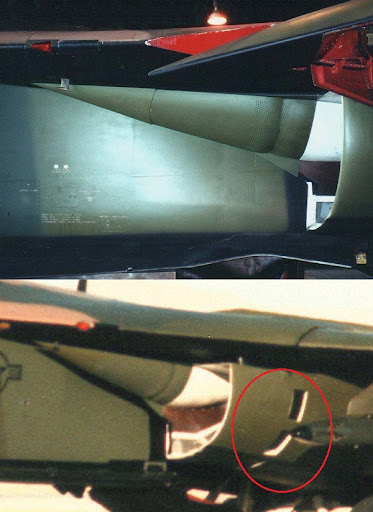
Regrettably, the airflow management of early intake models proved seriously deficient, resulting in compressor stalls and even flameouts at certain angles of attack. The problem would not be resolved for many years, during which several redesigned air intakes were tried and found wanting before the final configuration, known as ‘Triple Plow II’ (shown below), was adopted in the 1970’s. Note, in the second photograph below, the circled auxiliary air inlets in the side of the air intake, allowing a greater volume of air to reach the engines at low speeds for takeoff.
The F-111’s intakes are larger than they first appear, as may be seen in this photograph of a technician working inside one of them. Note the vortex generators, some of which are circled in red.
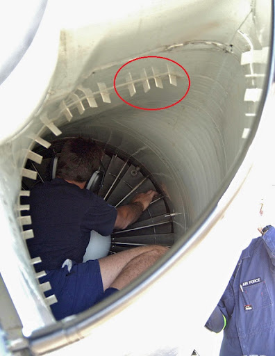
In addition to their aerodynamic problems, the low placement of the intakes meant that runway debris was easily kicked up into them by the nosewheel. This caused a number of accidents, and meant that the original design objective of operating the F-111 from rough, unprepared airstrips was never really feasible. In practice, the aircraft was restricted to long, hard-surface runways, which had to be carefully inspected for foreign objects before takeoff.
However, air intakes were not the only cause of problems with the TF30. Being the first engine of its kind in the world, it had ventured into unknown territory. Some of the metal alloys and other materials used in its construction proved unequal to the demands upon them, causing serious serviceability issues and maintenance headaches. Redesigned components would have to be introduced to replace them. Designers of subsequent engines would benefit from such experiences, but that didn’t help the TF30 to cope with the many demands upon it. It was used in initial models of the F-14 Tomcat fighter, but continued to prove less than fully satisfactory, and was eventually replaced in later models of that aircraft by more modern, more powerful and more reliable engines.
Nevertheless, let’s give credit where credit is due. As the first of its kind, the TF30 was a remarkable achievement, for all its problems. Despite its limitations, it’s continued to serve on the F-111 to this day (although requiring due care from pilots, who throughout the service life of the aircraft had to learn when they could ‘push’ their engines, and when it was best to be very cautious with their throttles).
NEW METAL ALLOYS
The variable geometry wings and turbofan engines of the F-111 posed entirely new challenges to engineers in terms of finding metals that would stand up to the stresses involved. They succeeded . . . but not before numerous problems that almost destroyed the program.
Originally it was intended to use titanium for many airframe components. Titanium is extremely light, very strong, and offers excellent heat resistance. Unfortunately, it also poses many difficulties, not least of which is its very high price. Cadmium-plated tools (common in production environments) interact with titanium parts, meaning they can’t be used. Titanium must be heat-treated before use, an added complication, and is so hard that it dulls drill bits prematurely. Titanium also reacts with oxygen in the air during welding, meaning that it can only be welded in a nitrogen environment. All these factors made it cost-prohibitive to use titanium for the F-111.
Therefore, it was decided to use steel and aluminum alloys for the project. Unfortunately, the steel alloy selected, known as D6AC, was new and relatively untried in aircraft production. Furthermore, the aluminum was not in sheet form (which was well understood in the aerospace industry of the day), but in honeycomb panels that would be layered onto the fuselage frames. This was certainly innovative and efficient, but it was also untried, new technology. General Dynamics would encounter enormous problems in resolving all of the difficulties raised by such new approaches.
A particular problem, one that almost destroyed the program, was the wing carry-through structure in the fuselage (incorporating the gearbox that swept the wings forward or back). Extensive modifications and changes in material were incorporated during development, but these proved inadequate.To add to the project’s woes, it was later found that the manufacturer of the wing carry-through box, Selb Manufacturing Corp., had bribed production-line quality-control inspectors to approve unauthorized weldings. This was only discovered after many F-111’s had already entered service. The fleet was immediately grounded. (Selb was subsequently convicted on criminal charges, and was successfully sued by General Dynamics for civil damages.)
In December 1969, an F-111 experienced a catastrophic wing failure during a pull-up from a simulated bombing run at Nellis Air Force Base. This aircraft only had about 100 hr of flight time when the wing failed. The failure originated from a fatigue crack, which had emanated from a sharp-edged forging defect in the wing-pivot fitting. As a result of the accident, the Air Force convened several special committees to investigate the failure and recommend a recovery program. James C. Newman, Jr. and Herbert F. Hardrath represented Langley on the recovery team deliberations, and along with Charles M. Hudson and Wolf Elber, they conducted fatigue crack growth and fracture tests on specimens made from the D6ac steel used in the aircraft. These tests were conducted in the Langley Fatigue and Fracture Laboratory under conditions that simulated aircraft operations. The original material had low fracture toughness due to the heat-treatment process. The committee recommended that every F-111 be subjected to a low-temperature proof test. This proof-test concept had been developed and successfully used in the Apollo program, as well as other missile and space efforts. To screen out the smallest possible flaw size, the F-111 full-scale proof tests were conducted at temperatures of about -40¾ F, where the fracture toughness of the D6ac steel was lower than the fracture toughness at room temperature. The heat-treatment process was also corrected to provide improved toughness for the D6ac material in newer aircraft. … As a result of the revised proof-test approach and the improved toughness material, there were no F-111 aircraft lost due to structural failure in almost 30 years of operations before the aircraft was retired from service in 1996.
The F-111 failure was most responsible for the U.S. Air Force developing the damage-tolerant design concept, where flaws, such as a 0.05-in. crack, are assumed to exist in critical aircraft components. The structural components must then be tolerant of these defects during flight conditions. This concept relies on fatigue crack growth and fracture criteria to establish an inspection interval to insure the safety and reliability of the aircraft.
The USAF continued its Cold Temperature Proof Testing program until it retired the last of its F-111’s in 1998. The RAAF used USAF facilities to test their F-111’s, and built their own test facility after the USAF’s closed down. An interesting technical account of their procedures and experiences ‘down under’, which were of course similar to those of the USAF, may be found here.
AUTOMATED NAVIGATION AND WEAPONS DELIVERY SYSTEMS
The USAF wanted the world’s most sophisticated navigation and weapons delivery system on its new strike aircraft. Different components provided for communications, navigation, terrain following, target acquisition and attack, and suppression of enemy air defense systems. A radar bombing system was required for use at night or in bad weather.
To satisfy these requirements, different companies developed components that were then integrated into an overall system. The Mk I avionics system in the first production models included a Litton AJQ-20 inertial navigation and attack system, a General Electric AN/APQ-112 attack radar, a Honeywell APN-167 pulsed-type radar, a Texas Instruments AN/APQ-110 terrain-following radar, and Collins ARC-109 UHF and ARC-112 HF radio transceivers. Electronic countermeasures systems included the ALE-28 chaff/flare dispenser, APS-109 radar-warning receiver (RWR), and Sanders Associates ALQ-94 noise/deception set.
The terrain-following radar (TFR) was integrated into the automatic flight control system, allowing for “hands-off” flight at high speeds and low levels (down to 200 ft). The system allowed the aircraft to fly at a constant altitude, following the Earth’s contours through valleys or over mountains, day or night, regardless of weather conditions. If any of the system’s circuits failed, the aircraft automatically initiated a climb.
It proved very difficult to develop and integrate the various components involved. However, the result was (at the time) the finest navigation and weapons delivery system in the world. It was so good that it would not be surpassed until the 1980’s, with the B-1 Lancer program. Indeed, the Soviet Union and China sought (and obtained) the wreckage of F-111’s shot down over North Vietnam in the early 1970’s, in order to reverse-engineer their systems. In particular, China tried to do so (unsuccessfully) for its later-canceled Nanchang Q-6 project.
Later versions of the F-111 would employ upgraded avionics and weapons systems, which are too numerous to describe here. They would also employ external weapons guidance systems such as the AN/AVQ-26 Pave Tack target designator pod, shown below, in conjunction with laser-guided bombs.
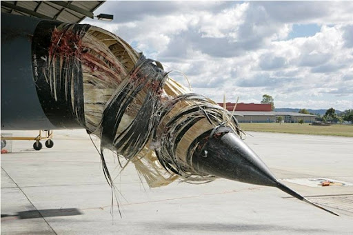
While we’re speaking of low-level flight, this is a good time to note that such flying involves a greatly increased risk of bird strikes. The photograph below shows a RAAF F-111 that suffered a bird strike to the side of its radome (the luckless bird bounced off and continued down the side of the aircraft into the engine intake). Notice how the radome’s construction of woven synthetic fibers (chosen for their light weight and transparency to radio and radar emissions) has ‘unraveled’ due to the impact.
The impressions of a USAF pilot who suffered a bird strike during a flight in an F-111 may be read here.
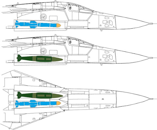
The internal bay of the F-111 was designed to carry a pair of nuclear weapons, either the B43, B57, B61 or B83 free-fall bombs or the AGM-69 SRAM missile. The bay could be used for conventional bombs as well, accommodating two of the 500-pound Mk. 82, the 1,000-pound Mk. 83, the 2,000-pound Mk. 84 or the M118 3,000-pound weapons (although in actual operations the latter two bombs were never carried internally, but beneath the wings, as a Pave Tack laser designator pod would be fitted inside the bomb bay). The diagrams below show the location of the bomb bay within the F-111’s fuselage, and how weapons would be mounted in it.
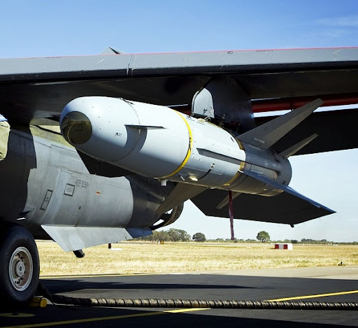
Auxiliary fuel tanks could be carried in the bay instead of bombs, or a 20mm. M61 Vulcan cannon and 2,000 rounds of ammunition could be fitted there. (The cannon was primarily intended for air-to-air combat by the US Navy’s F-111B fighter-optimized version, which was subsequently canceled.) As far as I know, the cannon was never carried operationally by USAF or RAAF F-111’s. RAAF aircraft were also equipped to carry the AGM-84 Harpoon anti-ship missile and the AGM-142 Popeye/Have Nap, shown below.
Two stations were provided beneath the aircraft to carry electronic countermeasures (ECM) pods and/or datalink pods. One was beneath the weapon bay (shown earlier in the photograph of an F-111 with a Pave Tack designator pod, which was always mounted on this station), and the other on the rear fuselage, between and below the engines. Weapons could not be carried on these stations.
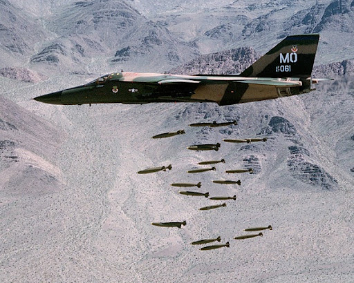
The F-111A could, in theory, carry up to 31,500 pounds of ordnance, although in practice only up to 20,000 pounds was usually loaded. The heaviest conventional bombing loads (such as were used in Operation Desert Storm) usually comprised up to 24 Mk. 82 500-pound bombs, carried on the four inner weapons pylons beneath the wings, or up to four laser-guided Mk. 84 2,000-pound bombs, with a laser designator mounted beneath the weapons bay. In the photograph below, an F-111 releases 24 Mk. 82 bombs during a training exercise.
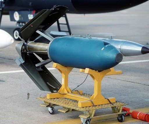
Sometimes, for very-low-level attacks, it was necessary to use bombs with braking or retarding devices, to ensure they fell sufficiently far behind the aircraft to avoid damaging it with their blast. A parachute retarding device was developed for the Mk. 82 bomb, as shown below.
A clamshell-type air-brake retarding device was also available, which could be retrofitted to any standard US bomb. One is shown below, fitted to a Mk. 117 750-pound high-drag bomb.
These apparently proved more reliable in service than the parachute devices, some of which are said to have failed to open.
CREW ESCAPE SYSTEM
As with so many other innovations in aircraft technology, the development of assisted escape systems for aircrew began in Germany, prior to and during World War II. Jim Griff’s excellent ejector seats Web site describes them as follows:
In Germany, developments in aeronautical technology were accelerating with the introduction of the jet engine, while by 1939, the Luftwaffe’s Aviation Medicine branch was actively experimenting with ejection systems, using physiological testing devices that included instruments for measuring the forces of gravity and acceleration on the human body. Their tests has determined rough physiological parameters of human ability to withstand G force onset of about +20G for a duration of about 0.1 second. The German preference was at this time for a compressed gas system of ejecting the aircrew seat, although explosive cartridge propelled seats were also under development. The need for adequate aircrew escape from dive-bombing aircraft such as the Ju-87 Stuka, with its sustained high positive G loading during pull-out, significantly motivated investigations into use of high-pressure systems to eject aircrew. The German manufacturer Heinkel maintained chief engineering responsibility for development of all aircraft escape systems, throughout the war, and by late 1942 all German experimental aircraft being flight tested were equipped with some form of Heinkel ejection seat.
With aircraft development feverishly continuing in wartime Germany, Heinkel-developed ejection seats finally started being installed in production aircraft, as radical new designs came into use. Although the singular Messerschmitt 262 twin-engined production jet fighter-bomber (Schwalb) did not feature such a schleudersitzaparat (the German term for ‘ejection seat’, which translates roughly to “seat catapult device”), reports suggest that at least a few versions (Sturmvogel) had what has been described as a catapult-seat (although it is not clear whether the seat was driven by an explosive charge or by a spring mechanism). Other aircraft, such as the Heinkel He-162 Volksjäger, were provided with a compressed air propelled ejection seat. Other aircraft to feature similar systems included the Dornier Do-335 Pfeil, the Arado Ar-234B Nachtigal, the Heinkel He-177, the Heinkel He-219 Uhu, the DFS-228, and the rocket-powered Messerschmitt Me-163 Komet (this last system was spring powered). Additionally, earlier research begun in the late 30s by Heinkel had resulted in the first recorded example of a completely ejectable crew compartment being developed. The rocket-powered Heinkel He-176 (the world’s first rocket propelled aircraft) featured a nose section which could be jettisoned in the event of an emergency. Development problems involving successful deployment of the main parachute designed to slow descent of the ejected crew compartment resulted in several innovative engineering designs, and subsequent testing demonstrated that in the event of the crew being disabled, the He-176’s crew compartment would enable its occupant to survive a landing within the escape pod with only minor injuries.
There’s more on the history of ejection seats and capsules at the link. Very interesting reading.
Ejection seats were used in most jet-powered combat aircraft from the late 1940’s onward. By the early 1960’s their technology was mature, but was also proving to be inadequate for the very high speeds and altitudes then being attained. Wind blast and oxygen starvation injured or killed a number of pilots. Clearly, an improved crew ejection system was needed, particularly for an aircraft like the F-111. It would operate from very low level to very high altitude, from zero to more than 60,000 feet, and from subsonic to high-supersonic speeds. (Indeed, the F-111 proved to be the second-fastest aircraft ever developed in the Western world during the 20th century: it had a sustained high-altitude speed of Mach 2.6, second only to the famous SR-71 Blackbird, which cruised at Mach 3+.) Its crew might have to abandon the aircraft at any point in this extraordinarily wide flight envelope.
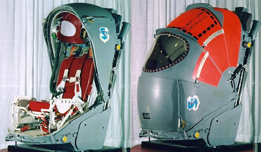
In the late 1950’s Stanley Aviation developed an encapsulated ejection seat (shown below) for the B-58 Hustler supersonic bomber.
It closed a clamshell-like protective covering over the crew member before he abandoned the aircraft, protecting him from high-speed wind blast and buffeting during the ejection process. It contained survival equipment for use after landing, including food, flotation gear for use at sea, etc. An excellent description of its operation, including more pictures and diagrams, may be found here. Unfortunately, it did not always prove reliable in service, but being the first of its kind to be developed, that’s perhaps not surprising.
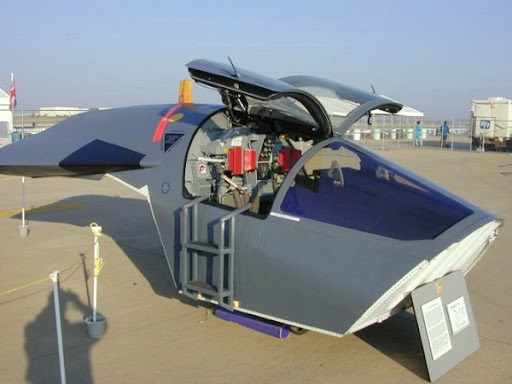
General Dynamics developed this idea further. Someone there came up with the very bright idea that if the entire crew compartment was ejected intact, no retractable shields or other devices would be necessary. The F-111’s crew compartment was therefore designed to be blasted free of the aircraft, remaining sealed against the environment and deploying its own parachutes for descent.
The pod was later used for training, then restored for display purposes.
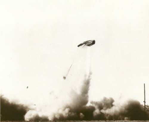
The capsule was fully pressurized. The pilot and navigator sat side-by-side in a ‘shirt-sleeve’ environment, needing neither oxygen masks nor pressure suits. In the event of an emergency, the entire pod was fired from the aircraft by a powerful rocket motor, which could function at any point in the flight envelope, from zero-zero (i.e. zero speed and zero altitude, with the aircraft standing still on the ground) all the way to maximum speed and altitude (Mach 2.6 at 60,000-plus feet).
parachute already deployed below and behind the capsule.
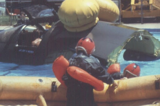
The capsule would then descend to earth under its own parachute, with the crew still safely inside. It would float in water, with the added assistance of inflatable flotation bags, or provide a shelter on land until the crew could be rescued. Survival equipment was carried in the capsule to cater for almost any emergency.
being used for aircrew training in a swimming-pool.
Note the inflated flotation bags behind the cockpit.
The capsule proved difficult and time-consuming to develop. The first F-111’s flew with conventional ejection seats, as the capsule could not be finished in time. However, the eleventh and subsequent F-111’s received the capsule on the assembly line, and earlier aircraft were retrofitted with it.
Despite its complexity, the escape capsule proved highly successful in operation, saving the lives of many aircrew over the service life of the aircraft. The only problem encountered was that impact forces on landing were very high, sometimes measured at over 30 g’s, which caused injuries to some survivors. However, considering the alternative, one suspects they put up with the injuries relatively cheerfully!
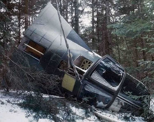
The capsule below is from an FB-111A which crashed in Vermont on February 2nd, 1989. The pod landed safely one mile from the crash site. The crew escaped without serious injury.
We’ve looked at the development of five of the F-111’s most complex systems and structures. Next week, in Weekend Wings #38, we’ll examine the testing and operational deployment of this aircraft; how problems with these and other systems were overcome; and how the F-111 became one of the premier strike aircraft of its day.
Peter











Well done Peter! If you were to compile these stories into a book, you can be sure I'd buy a copy.
Jim
Awesome entry, Peter. I'll miss the F111, they were a familiar sight Down Under and a beautiful aircraft to watch. Got heaps of photos of them in my days in the RAAF.
I'll never forget in 2000 when one F111 took off from Amberley Qld and went super-sonic to reach Sydney in time for an after-burner pass in the Olympics opening. It took less than 20 mins to reach us!
At the time I lived in the NW suburbs of Sydney directly under their flight path. We heard those superb engines slowing down, then speeding up again as they passed over us on their way to the stadium fly-by. Will never forget it.
Mind you: one aspect of the F111 that receives little publicity is the extremelly poisonous fuel it used. To this day the maintenance crews suffer from its after-effects: not many left alive…
But I'll miss this wonderful plane. It was truly a landmark of aviation.
Well done Peter. You demonstrate your writing abilities very well with this exhaustive article. I appreciate your efforts. Cheers
Great job. First model I ever built was of an F-111
Excellent post Peter! The real 'fun' with the Vark was the TFR and the ride selections 🙂 Excellent research and excellent links also!
My family moved to Fort Worth in mid-1992. Big news was the then-pending award of the TFX contract to General Dymanics, which most locals still called Convair, or even Colsolidated. This was the famous "Bomber Plant," which had been a major part of the industrial effort in WW-II, and a huge factor in the local economy.
That fall, I started college at TCU and enrolled in AFROTC. The GD plant and Carswell AFB were major benefactors to that program. During one of the initial films of the low level, terrain following program, several cadets became motion sick, sitting in the auditorium.
I remained in Fort Worth until 1972. Though I never had any direct connection with the TFX/F111/FB111, your excellent article brought back many memories. Well done, Peter, and I look forward to the next installment.
JPG
Excellent article on the F-111.
I was a Munitions Officer on it in 1969-1970. The aircraft actually has 4 vs. 3 pylon attachment points on each wing. The 2 inboard pylons swivel; the 2 outboard pylons are fixed. In theory you could load 48 750-pound bombs (M-117s) on the wings; and 2 in the bomb bay. You couldn't sweep the wings in this configuration, and with the fixed pylons, the aircraft wasn't as maneuverable, or as fast.
A "PS" (post script) that has been with me for many years: In school "they" told us that the F-111 had a 'gas agent' dispersal capability. I always thought what a great platform for forest firefighting in remote areas.
With the agent dispersal capability, coupled with TFR, the aircraft could get in to places where airliners (configured for firefighting) struggle… Of course the operating costs would have to be measured against the benefits, and "parochial thinking…"
Cheers,
RF Holliker
November 28, 2010 5:46 AM
Thanks Peter, that was an exceptional post.
As a boy rowing on a coastal lagoon one overcast day, I watched in awe as a three ship formation came in over the dunes a couple of hundred feet up. Directly overhead they swept back their wings, banked 90 degrees and headed on down the coast. I've no memory of the sound, just a perfect silent video in my head of the power and beauty of flight.
20 years later I stood on the ocean cliffs of Sydney and watched a pair fly past below me, avoiding controlled airspace by flying below ground level.
Although often called the Pig in Australian Service from this civilan observers viewpoint they were anything but.
Thanks Peter, great article with lots facts to help soften the bad rap the F-111 received. I worked on F-111s most all of my USAF career from 1967 to 1990. One point, about the Vulcan Canon, during Combat Lancer operations in 1968 the gun was operational and armed for combat missions but to the best of my knowledge it was never fired. After combat operations in 1968 I believe the gun was deactivated but retained for weight and ballast. Also, during this time our aircraft carried an AIM-9 missile in the weapons bay on a trapeze that could be extended below the bay enclosure for firing, but again to my knowledge it was never fired and soon the trapeze was removed from all aircraft.
I'm looking forward to seeing the next article. Keep up the fine work.
I think you're wrong on the pivot points. The X-5, as can be seen on the pic you provided, moved the pivot points forward as the wings were swept, and vice-versa. This kept the C. of L. in nearly the same place, but made the system either heavy or weak (pick one). The big discovery, as I recall reading at the time, was that you could have a fixed pivot and it would work OK if sufficiently outboard.
awsome post, I remember the strike on tripoli back in the 80's where this bird did all the leg work.
Fabulous article. As to the the Vulcan cannon I worked on the F-111-F at Mountain Home AFB around 1975 when we were still receiving new aircraft from the factory. We had the gun installed and operational. In fact our pilots fired the gun on a regular basis in training. We also loaded dummy Aim-9's Mr. Noons reference to poisonous fuel is bogus The fuel was standard JP-4 Jet fuel
You quite right, Alan: it wasn't the fuel, it was the tank "blister" maintenance chemicals.
Here:
http://www.abc.net.au/am/content/2008/s2219224.htm
There is a lot more on that subject. The government has recently opened a special grant for the maintenance crews.
Yet another great write-up, BRM. I know the XB70 never made it into production, but wasn't it a little faster than the F-111?
Yes, the XB-70 was faster – as fast as the SR-71 – but, as you point out, it never entered production, so I don't count it as a 'service' aircraft, merely a very interesting experiment in what might have been.
Hi Peter!
Great Blog!! The reason I'm writing is I'm looking for info on a collision between an F-111F 70-2384 and a KC-135E 59-1484 during the first few days of Desert Storm. The tanker was from the PA ANG. I was based at Jeddah, Saudi Arabia and saw the damaged tanker when it returned. The F-111F returned to its home base (Taif, I think) with a damaged right wing tip. Do you or any fellow F-111F enthusiasts know any more about this incident? Thank you!
Dennis Schneider
dennis220@centurytel.net
(509) 299-4136
Dennis, I hadn't heard about any such incident. After reading your comment, I did a quick search, which turned up this forum thread:
http://www.nntpnews.info/threads/6757165-Were-there-any-KC-135-Tankers-shot-down-in-desert-storm
I don't know whether the incident reported there is the one to which you refer.
Hi Peter,
Yes, I've seen that site, which doesn't say much. This incident really did happen. There are two unofficial versions: (1) It was a night refueling of two receiver a/c and the a/c pilot on the port position became disoriented and drifted into the tanker; and, (2) the two receiver a/c decided to depart by diving under the tanker, accelerate below it, and then do an AB climbout in front of the tanker. The port a/c, however, came up too soon, thus striking the tanker. The gash in the tanker fuselage caused an instantaneous decompression, which resulted in a cargo cabin full of loose papers and debris. I saw a picture of the cabin while in Jeddah, but haven't seen it since. Funny thing is, the few F-111 enthusiasts I've contacted have never heard of this incudent! HHMMMMMM!!!
Dennis Schneider
Thanks for the site. Two years on, I still miss them.1100 hours, fifteen years of my life. Great jet, good work on the web site. Recce rules OK!!!
Doc
Good read Peter but you left out a little about the design and purpose of the spoilers on the wings. Not only did all four extend symmetrically on landing roll to destroy lift and assist in slowing the aircraft but they also extended asymmetrically when roll commands were inputted by the flight crew to decrease lift on just one wing and increase roll response. The inboard pair was locked down at 45 degrees of wing sweep and the outboards at 47 degrees.
I don't know what Noons was talking about the F-111 fuel being "highly poisonous"…in the US they used standard JP-4 Jet Fuel (mostly kerosene). Perhaps he is thinking of the Hydrozene fuel used in the APU's of F-16's???
Charlie, ex F-111 & F-117A B-Shop Troop
These came out when I was a kid.
One of the most beautiful jets ever.
That and the B-1.
And the F-4
And the F-14
And the F-18
And the A-6.
And the F-104
Okay, so I guess I think a bunch of them are sharp…
– Charlie
Peter, I was an Air Force wife in the 80's-90's. My husband was an E-F111 pilot at Mountain Home and RAF Upper Heyford. A close friend died in combat and we were told it was because of an ejection failure due to the uncompensated weight difference between the pilot and the EWO (who was very small). Because their weight wasn't distributed evenly they didn't have the benefit of the inflatable collar/cushion. What do you think?
@Anonymous on June 9, 2014 at 6:03 AM:
I really can't answer that question. I'm not sufficiently technically versed in the aircraft. You might do better to put it to one of the specialist sites, such as this one:
http://f-111.net/
I was a tower controller at Mtn Home 80-85, damn I love the 111. Hard to work in the pattern, not a fighter but what a plane. I got 2 rides, the first was blaaa, crappy pilot and SOF. The second ride, LtC McDonald, hell of a pilot/SOF. 650 kts, 89 ft AGL, OMG! Nothing goes as far, as fast. I asked many a SOF, "If you had to go into the USSR will you make it to your target"? 100% said YES! Talked to 2 Strike Eagle drivers that used to be 111 jocks, they said nothing could replace the ardvark!
great analysis of one of the greatest near failures of the 1960s. I always wondered about those glove flaps which were never shown on the prototypes and made a complex flap system even more complex. Those crazy rotating pylons, not only are the outer 2 of 4 fixed so that they aren't straight on takeoff (they are straight at the slight sweep cruise position) but of the inner 2, there is only room for one store or tank at full sweep, so the aircraft is almost never flown with stores at full sweep. There is no room under the fuselage for real hardpoints, unlike the F-14 which separated engines enough to leave a tunnel, but suffered from control problems if one engine went out. Real irony is that in effort to save money, very few F-111s were built, and the F-4 Phantom which ended up inheriting various traits of bombers, interceptors and day fighter (which was forced on the USAF by McNamara along with A7) the F-111 was supposed to replace was actually the only bird in history which actually flew with all 4 services in all missions and with most allies. The F-111 had no versatility as the USAF version had no all-weather missile sparrow capability and the naval version had no bomb delivery capability, could no operate from short unprepared fields, and was a worse dogfighter than the F-105 which was better replaced by the F-4.
Another interesting what-if is that the UK put Spey engines in the Phantoms, and they appear to be a higher thrust alternative to the TF-30 used in F-14 and F-111. The Spey was used in advanced A-7D variant without afterburner.
The featured F-111D capsule landed near Hope, New Mexico, on 10OCT76. The jet was on an FCF flight (functional check flight). The crew ejected during the supersonic phase. The tapes froze at 1.42 Mach. The crew survived to fly another day…a little battered but no injuries.
An hydraulic servo valve in the flight control system failed. The jet entered an uncontrolled rolling dive (some geek engineer figured in excess of 60,000 FPM rate of descent) from about 45,000 feet to the ejection altitude of about 15,000 feet. There were lots of negative G's. The WSO pulled the ejection handle saving the crew. Someone figured, att that descent rate, had they waited four more seconds they would not have made it.
The featured capsule training photo was taken at the officers club pool at Cannon AFB.